Contents:
- RiDeclare: new classes
- RiReadArchive
- RiProcedural: new forms
- RiCoordSysTransform
- RiPoints
- RiCurves
- RiNuCurves
- RiSubdivisionMesh
- RiDisplay: arbitrary output variables
- RiQuantize: separate alpha
- RiPixelFilter: new filters
- RiObjectFree and RiLightFree
- Inline token declarations
- gzipped RIB
- Client library extensions
Variables that are defined constant carry exactly one value per primitive. That value is ultimately passed to the shader as a uniform variable. Note that variables may not be declared "constant" in shaders.constant uniform varying vertex
Vertex variables carry one value per control vertex (e.g. "P"). These values are then handled and interpolated just like the control vertices themselves and are ultimately delivered to the shader as varying variables. Note that variables may not be declared "vertex" in shaders.
RenderDotC also supports three new variable types: vector, normal and hpoint. Vector and normal variables are like points except that they are transformed differently when projected to the "current" coordinate system of the shader. Homogeneous points contain four components (x, y, z, w) and may be declared using the hpoint type. After being projected to "current" coordinates, hpoints are divided through by w and delivered to the shader as regular points. There is not hpoint type in SL.
RiReadArchive(RtToken name, RtCallbackFunc callback, ...)In RIB:
RiReadArchiveV(RtToken name, RtCallbackFunc callback, RtInt n,
RtToken tokens[], RtPointer parms[]);
ReadArchive "name"The RIB version is essentially a #include. The C bindings provide an additional callback function. This feature is currently unimplemented.
RiCoordSysTransform(RtToken space)In RIB:
CoordSysTransform "space"The space may be predefined such as "object", "world", "camera", "screen", "NDC", or "raster". Alternatively, the space may have been defined earlier in the stream with a call to RiCoordinateSystem.
RiPoints(RtInt nverts, ...)In RIB:
RiPointsV(RtInt nverts, RtInt n, RtToken tokens[], RtPointer parms[])
Points parameterlistThe parameterlist must contain at least positional information "P" or "Pw". There is one position per point. The surface shader is evaluated only once per point, with P being right at the center. Other shader variables such as du, dv, and N are meaningless and should be ignored by the shader.
After being shaded, each point is rendered as a hexagon oriented to face the camera. This orientation may not be changed. Points should never be culled due to backfacing.
The diameter of each hexagon is specified in object coordinates (not pixels) and defaults to 1.0. If all points in a set are to be the same width, the "constantwidth" variable may be used in the parameterlist. Being declared "constant float", "constantwidth" takes one value regardless of the number of vertices. To set the width of each point independently, use the "width" parameter. It's a varying float and thus takes nverts distinct width values.
RiCurves(RtToken type, RtInt ncurves, RtInt nvertices[], RtToken wrap, ...)In RIB:
RiCurvesV(RtToken type, RtInt ncurves, RtInt nvertices[], RtToken wrap,
RtInt n, RtToken tokens[], RtPointer parms[]),
Curves "type" [nvertices] "wrap" parameterlistThe spine can twist smoothly around in 3D. Across the width of the curve (perpendicular to the spine) the primitive is always flat. For this reason, a narrow width is often chosen. If the primitive must curve across its width, a bicubic patch should be used instead.
The first argument must be either "linear" or "cubic" (note: not "bilinear" nor "bicubic"). A linear curve is really a 3D polyline with some thickness. Cubic curves obey the vbasis from the RiBasis function. The basis may be predefined such as bezier and b-spline, or it may be defined by the user.
The second argument says how many distinct curves to render. Unlike trim curves, there is no requirement that consecutive curves line up head to tail or form a closed loop.
The number of vertices in curve number i is given by nvertices[i]. For linear curves, the number of vertices may be any number greater than or equal to 2. For cubic curves, there must be four or more vertices in each curve. An additional constraint is put on the number of vertices in a cubic curve. A nonperiodic cubic curve must have (vstep * k + 4) vertices where k is an integer greater than or equal to 0 and vstep is the step size of the current v basis. A periodic cubic curve must have (nvstep * k) vertices for k greater than 0. For example, a nonperiodic Bezier curve may have 4 or 7 vertices but not 5 nor 6.
The wrap argument may be either "periodic" or "nonperiodic". Periodic curves automatically repeat the first (4 - vstep) vertices in order to form closed loops. If "periodic" is specified, every curve in the set will close on itself. Nonperiodic curves have two distinct ends.
The parameterlist must contain at least position data "P" or "Pw". If normals "N" are specified, the curve will twist to remain perpendicular to the N. This may cause part of the curve to face away from the camera. Becuase N is a varying variable, one value is given for each end of the curve and for every joint between consecutive curve segments. The normal is linearly interpolated in between. In the case of a cubic curve, this will be less than the number of vertices. If normals are not specified, the curve will automatically turn to face the camera for its entire length.
The width of the curve is specified in object coordinates (not pixels) and defaults to 1.0. If the curve is to have a uniform width, the "constantwidth" variable may be used in the parameterlist. Being declared "constant float", "constantwidth" takes one value regardless of the number of vertices. To make the width of the curve vary, use the "width" parameter. A width is given for each end of the curve and for every joint between consecutive curve segments. The width is linearly interpolated in between. For even greater control over the width of a curve, redeclare width as a vertex parameter:
Declare "width" "vertex float"
After that, specify a different width value for every vertex. The width will be linearly interpolated in between.
The surface shader will be evaluated many times along the length of the curve (in the v direction) and at least twice across the width (the u direction). For wide curves, it may be evaluated even more often across the width. All of the shading variables are meaningful within the shader including du, dv, and N. One caveat is that user vertex data is not interpolated across the width of curves. Instead, the same value is duplicated in the u direction. This means that the "make sticky" procedure is ineffective with curves if color variation across the curve width is important.
The number of values for each class of variable is as follows:
constant: 1 for entire RiCurvesWhere totalverts = sum(nvertices[i]) and
uniform: ncurves
varying: (totalsegs + ncurves) if wrap is "nonperiodic"
totalsegs if wrap is "periodic"
vertex: totalverts
sum(nvertices[i]) for periodic, linear curves
sum(nvertices[i] - 1) for nonperiodic, linear curves
sum(nvertices[i] / vstep) for periodic, cubic curves
sum((nvertices[i] - 4) / vstep + 1) for nonperiodic, cubic curves
RiNuCurves(RtInt ncurves, RtInt nvertices[], RtInt order[],In RIB:
RtFloat knot[], RtFloat min[], RtFloat max[], ...)
RiNuCurvesV(RtInt ncurves, RtInt nvertices[], RtInt order[],
RtFloat knot[], RtFloat min[], RtFloat max[], RtInt n,
RtToken tokens[], RtPointer parms[])
NuCurves [nvertices] [order] [knot] [min] [max] parameterlistNote the similarities between RiNuCurves and RiTrimCurves.
The spine can twist smoothly around in 3D. Across the width of the curve (perpendicular to the spine) the primitive is always flat. For this reason, a narrow width is often chosen. If the primitive must curve across its width, a nurb patch should be used instead.
The first argument says how many distinct curves to render. Unlike trim curves, there is no requirement that consecutive curves line up head to tail or form a closed loop.
The number of vertices in curve number i is given by nvertices[i].
The order of each curve must be positive and is equal to the degree of the polynomial basis plus 1. There must be at least order[i] vertices in curve number i.
Each curve has (nvertices[i] + order[i]) knots. These knots must appear in non-decreasing order. The knots for all of the curves are concatenated into a single array.
Each curve is defined in the parametric space from min[i] to max[i]. Each min[i] must be less than max[i]. Also, min[i] should be greater than or equal to the corresponding (order[i] - 1)th knot value and max[i] should be less than or equal to the (nvertices[i])th knot value for curve i.
The parameterlist must contain at least position data "P" or "Pw". If normals "N" are specified, the curve will twist to remain perpendicular to the N. This may cause part of the curve to face away from the camera. Becuase N is a varying variable, one value is given for each end of the curve and for every joint between consecutive curve segments. The normal is linearly interpolated in between. If normals are not specified, the curve will automatically turn to face the camera for its entire length.
The width of the curve is specified in object coordinates (not pixels) and defaults to 1.0. If the curve is to have a uniform width, the "constantwidth" variable may be used in the parameterlist. Being declared "constant float", "constantwidth" takes one value regardless of the number of vertices. To make the width of the curve vary, use the "width" parameter. A width is given for each end of the curve and for every joint between consecutive curve segments. The width is linearly interpolated in between. For even greater control over the width of a curve, redeclare width as a vertex parameter:
Declare "width" "vertex float"
After that, specify a different width value for every vertex. The width will be linearly interpolated in between.
The surface shader will be evaluated many times along the length of the curve (in the v direction) and at least twice across the width (the u direction). For wide curves, it may be evaluated even more often across the width. All of the shading variables are meaningful within the shader including du, dv, and N. One caveat is that user vertex data is not interpolated across the width of curves. Instead, the same value is duplicated in the u direction. This means that the "make sticky" procedure is ineffective with curves if color variation across the curve width is important.
The number of values for each class of variable is as follows:
constant: 1 for entire RiNuCurvesWhere totalverts = sum(nvertices[i]) and
uniform: ncurves
varying: (totalsegs + ncurves)
vertex: totalverts
RiSubdivisionMesh(RtToken scheme, RtInt nfaces,
RtInt nvertices[],
RtInt vertices[], RtInt
ntags, RtToken tags[], RtInt nargs[],
RtInt intargs[], RtFloat
floatargs[], ...)
RiSubdivisionMeshV(RtToken scheme, RtInt nfaces,
RtInt nvertices[],
RtInt vertices[], RtInt
ntags, RtToken tags[], RtInt nargs[],
RtInt intargs[], RtFloat
floatargs[], RtInt n, RtToken tokens[],
RtPointer parms[]);
In RIB:
SubdivisionMesh scheme [nvertices] [vertices]
{[tags] [nargs] [intargs]
[floatargs]} parameterlist
In all cases, scheme must be "catmull-clark".
At the top level, a subdivision mesh consists of a set of faces. The number of faces is given by nfaces. The nvertices[] array says how many vertices make up each face. The length of the nvertices[] array is nfaces. Next is the vertices[] array, containing a 0-based index into the vertex data of the parameter list for each vertex of each face. The length of the vertices[] array is equal to the sum of all the elements of the nvertices[] array. This part of the syntax is identical to RiPointsPolygons.
Additional subdivision control is provided through "tags". RenderDotC
currently implements the tags in the following table. Additional
tags may not be defined by the user (i.e. the set of available tags is
fixed by the renderer).
| Tag name: | Applies to: | Integer arguments: | Float arguments: |
| "hole" | faces | n | 0 |
| "corner" | vertices | n | 1 or n |
| "crease" | chain of edges | n | 1 |
| "interpolateboundary" | mesh | 0 | 0 |
["hole"] [2 0] [2 6] []
[This example and those below are excerpts of just the tag information. A complete example would start with "SubdivisionMesh" and end with "P" followed by the positions of the control mesh.]
Reading left to right, this says that tag "hole" takes 2 integer arguments and 0 floating point arguments. The integer arguments are 2 and 6, the indeces of the faces to be tagged as holes. There aren't any floating point arguments, so the final list is empty.
If there are no tags at all, then all of the tag parameters may be omitted in the RIB binding.
An example:
["corner"] [4 1] [0 1 4 5] [10]
This tags vertices 0, 1, 4, and 5 as infinitely sharp.
For example:
["crease"] [5 1] [0 1 4 5 0] [10]
This marks a loop of 4 edges as infinitely sharp creases.
["interpolateboundary"] [0 0] [] []
["hole" "corner" "crease" "interpolateboundary"] [2 0 4 1 5 1 0 0] [2 6 0 1 4 5 0 1 4 5 0] [10 10]
Compare this example to those above to see how it was constructed.
RiDisplay supports a new syntax for specifying multiple simultaneous display streams. Initially, the list of display streams is empty. If the first parameter of RiDisplay starts with a plus sign '+', then the display stream is added to the current list. There is no arbitrary limit on the maximum number of display streams. If the name follows the old syntax and does not start with a plus sign, then the list is cleared before adding the new display. For example:
RtString midpoint = "midpoint";Note that it's acceptable for every RiDisplay to begin with a '+' including the first. The way the rules are worded, the list is initially empty and you can just start adding to the list using the plus sign syntax. If there are no Display commands at all, Display "RenderDotC" "framebuffer" "rgb" is added by default at WorldBegin. If any argument to RiFormat is negative, default values are queried from the first display driver in the list.
RiDisplay("patch.tif", "file", "rgb", RI_NULL);
RiDisplay("+patch.z", "zfile", "z", "filter", &midpoint, RI_NULL);
Besides the standard combinations of "rgb", "a", and "z", the mode parameter may be any of the following RenderMan globals:
P, N, Ng, dPdu, dPdv, Ci, Oi, s, t, u, v, du, dv, Cs, or OsMode may also be the name of a shader variable declared as "output" in the surface shader. In this case, the variable must be RiDeclared before it is referenced in RiDisplay, and the type must be point, vector, normal, float, or color. The global variables in the list above are predeclared by RenderDotC and do not need to be redeclared. If no surface shader output variable with a matching name is found, then the display channel will be filled with zeros.
Output variables of type color are hidden just like "rgb" in that partially transparent objects attenuate the color of the objects behind them. Variables of all other types (float, point, vector, and normal) are only affected by the closest surface, regardless of its opacity.
Again, the first RiDisplay is as flexible as subsequent displays. The mode of the first display can be any of the above, not just rgb/a/z. Subsequent displays can also have any mode, including rgb/a/z.
In surface shaders
To export a shader variable for display, declare it as "output" in a surface shader:
surface glow(output varying color Cg = 0;Variables output from non-surface shaders (e.g. displacement) may not be displayed. Uniform output variables are acceptable. They will be promoted to varying by the renderer at display time.
output varying color Og = 0)
Exposure
The traditional RiExposure command now affects only display streams with mode "rgb". The exposure of any channel may be explicitly set with the "gain" and "gamma" parameters:
Display "name" "driver" "var" "gain" [1.5] "gamma" [2.1]The default value for both gain and gamma is 1.0 except for "rgb" display streams, which get their defaults from RiExposure.
Quantization
The recommended way to set the quantization of a display stream is explicitly in the Display command:
Display "name" "driver" "var" "quantize" [zero one min max] "dither" [ampl]Where zero, one, min and max are integers and ampl is floating point. This is the only way to specify a value for zero other than 0.0 (the RiQuantize command only sets one, min, max, and ampl). The classic example of a case where zero might not equal 0.0 is when displaying normalized vector data. Each component of a normalized vector ranges in value from -1.0 to 1.0. To display such data on a 24-bit framebuffer:
Display "vector" "framebuffer" "Nf" "quantize" [128 255 0 255] "dither" [0.5]This will map -1.0 to black, 0.0 to gray, and 1.0 to white.
If the quantization parameters are not specified in the Display command, the renderer honors an Quantize command whose type matches the mode of the Display:
Declare "Cg" "varying color"The Quantize command must appear after the corresponding Display command.
Display "+glow.tif" "tiff" "Cg"
Quantize "Cg" 65535 0 65535 0.5
For display streams where neither of the above methods is used, quantization defaults to the values specified in Quantize "rgb" or Quantize "z" depending on the choice of filter (see below).
Filtering
The PixelFilter command sets the default filter kernel and filterwidths for all display streams. Individual display streams may be filtered differently by passing parameters to the Display command:
Display "name" "driver" "var" "filter" ["sinc"] "filterwidth" [4 4]This display stream will be treated as a depth channel if filter is set to "min", "midpoint", "average" or "max". Depth channels may be hidden, quantized, and filtered differently than other channels. For example, surfaces whose opacity does not meet the zthreshold option are ignored when hiding depth channels. For non-depth channels, choices for filter include "bartlett", "bessel", "catmull-rom", "disk", "gaussian", "sinc", and "triangle".
Each display stream may have different filterwidths, the largest of which impacts how much "off-screen" geometry needs to be considered by the hider.
RiQuantize(RI_RGB, 4095, 0, 65535, 0.5);
RiQuantize(RI_A, 65535, 0, 65535, 0.5);
For an understanding of why this might be useful, see Color Quantization For Film.
Specifying the type RI_RGBA is equivalent to setting RI_RGB and RI_A to the same parameters:
RiQuantize(RI_RGBA, 65535, 0, 65535, 0.5);
is equivalent to:
RiQuantize(RI_RGB, 65535, 0, 65535, 0.5);
RiQuantize(RI_A, 65535, 0, 65535, 0.5);
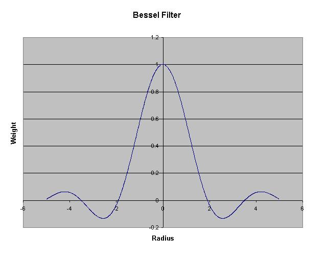
RiPixelFilter(RiBesselFilter, 4, 4);
RiPixelFilter(RiDiskFilter, 2, 2);
RiPixelFilter(RiBartlettFilter, 4, 4);
Or, in RIB:
PixelFilter "bessel" 4 4
PixelFilter "disk" 2 2
PixelFilter "bartlett" 4 4
Like the Sinc and Catmull-Rom filters, the Bessel filter is not widened
or narrowed by adjusting xwidth and ywidth. Rather it is clipped:
the filter retains it shape and is only evaluated over the bounds determined
by xwidth and ywidth.
The Disk filter is identical to the Box filter except that it is elliptical
when viewed from above (round if xwidth equals ywidth). The Box filter
is square.
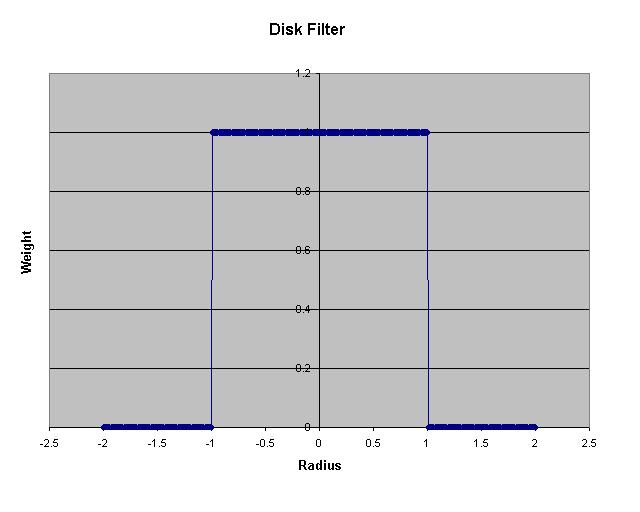
The Disk filter shown in the figure above is for xwidth = ywidth =
2.
The Bartlett filter is identical to the Triangle filter except that it is separable (i.e. the product of two 2D triangle filters). Along the x and y axes, the Triangle and Bartlett filters are identical. Along diagonals such as x = y, Bartlett becomes parabolic.
RtObjectHandle handle;In RIB, a user-provided integer is used for the handle:
handle = RiObjectBegin();
...
RiObjectEnd();
RiObjectInstance(handle);
...
RiObjectFree(handle);
ObjectBegin 7Likewise, lights may be freed when no longer needed:
...
ObjectEnd
ObjectInstance 7
...
ObjectFree 7
RtLightHandle handle;Or, in RIB:
handle = RiLightSource(...);
...
RiLightFree(handle);
LightSource "barn" 4 ...There are two circumstances where RenderDotC will automatically free lights and objects. The first is if the light or object is defined within a scope such as a Frame block or World block. When a scope ends, all lights and objects defined within it are freed. The second case is when an object handle is reused in the RIB binding. Because the new use of the handle will hide the old one, the old object is automatically freed. Reusing light handles does not cause the light to be freed because the old light may still be in the illuminated list. No harm is caused if a light or object is manually freed prior to when it would be automatically freed. It is an error to instantiate an object after it has been manually freed or gone out of scope. It is also an error to manually free a light or object after it has been automatically freed.
...
LightFree 4
Surface "hair" "uniform color rootcolor" [0.15 0.05 0.01]The syntax of the declaration is similar to that of RiDeclare except that the name of the token appears at the end of the declaration string.
The renderdc program is now capable of directly reading gzipped RIB. The program catribdc can be used to translate between ASCII, binary, and gzipped RIB.
RiBlobby(RtInt nleaf, RtInt ninst, RtInt inst[], RtInt nflt,It also recognizes the "mpoint" token type used by the RiBlobby primitive.
RtFloat flt[], RtInt nstr, RtToken str[], ...)
RiBlobbyV(RtInt nleaf, RtInt ninst, RtInt inst[], RtInt nflt,
RtFloat flt[], RtInt nstr, RtToken str[], RtInt n,
RtToken tokens[], RtPointer parms[])
RtContextHandle RiGetContext(void)
RtVoid RiContext(RtContextHandle context)
RiArchiveRecord("verbatim", ...)